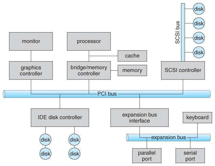
Figure 13.1 - A typical PC bus structure.
Figure 13.1 - A typical PC bus structure.

Figure 13.2 - Device I/O port locations on PCs ( partial ).
13.2.1 Polling
- One simple means of device handshaking involves polling:
- The host repeatedly checks the busy bit on the device until it becomes clear.
- The host writes a byte of data into the data-out register, and sets the write bit in the command register ( in either order. )
- The host sets the command ready bit in the command register to notify the device of the pending command.
- When the device controller sees the command-ready bit set, it first sets the busy bit.
- Then the device controller reads the command register, sees the write bit set, reads the byte of data from the data-out register, and outputs the byte of data.
- The device controller then clears the error bit in the status register, the command-ready bit, and finally clears the busy bit, signaling the completion of the operation.
- Polling can be very fast and efficient, if both the device and the controller are fast and if there is significant data to transfer. It becomes inefficient, however, if the host must wait a long time in the busy loop waiting for the device, or if frequent checks need to be made for data that is infrequently there.
13.2.2 Interrupts
- Interrupts allow devices to notify the CPU when they have data to transfer or when an operation is complete, allowing the CPU to perform other duties when no I/O transfers need its immediate attention.
- The CPU has an interrupt-request line that is sensed after every instruction.
- A device's controller raises an interrupt by asserting a signal on the interrupt request line.
- The CPU then performs a state save, and transfers control to the interrupt handler routine at a fixed address in memory. ( The CPU catches the interrupt and dispatches the interrupt handler. )
- The interrupt handler determines the cause of the interrupt, performs the necessary processing, performs a state restore, and executes a return from interrupt instruction to return control to the CPU. ( The interrupt handler clears the interrupt by servicing the device. )
- ( Note that the state restored does not need to be the same state as the one that was saved when the interrupt went off. See below for an example involving time-slicing. )
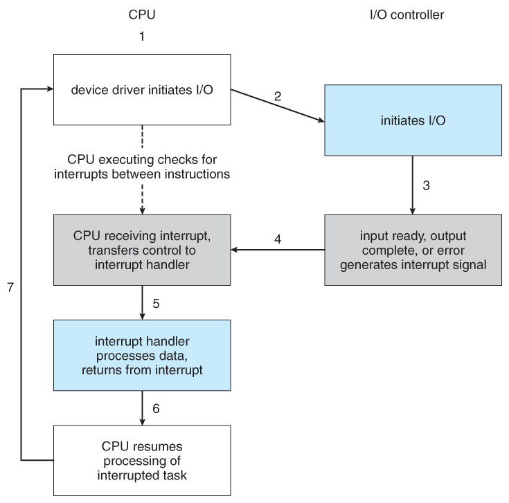
- Figure 13.3 illustrates the interrupt-driven I/O procedure:
Figure 13.3 - Interrupt-driven I/O cycle.
- The above description is adequate for simple interrupt-driven I/O, but there are three needs in modern computing which complicate the picture:
- The need to defer interrupt handling during critical processing,
- The need to determine which interrupt handler to invoke, without having to poll all devices to see which one needs attention, and
- The need for multi-level interrupts, so the system can differentiate between high- and low-priority interrupts for proper response.
- These issues are handled in modern computer architectures with interrupt-controller hardware.
- Most CPUs now have two interrupt-request lines: One that is non-maskable for critical error conditions and one that is maskable, that the CPU can temporarily ignore during critical processing.
- The interrupt mechanism accepts an address, which is usually one of a small set of numbers for an offset into a table called the interrupt vector. This table ( usually located at physical address zero ? ) holds the addresses of routines prepared to process specific interrupts.
- The number of possible interrupt handlers still exceeds the range of defined interrupt numbers, so multiple handlers can be interrupt chained. Effectively the addresses held in the interrupt vectors are the head pointers for linked-lists of interrupt handlers.
- Figure 13.4 shows the Intel Pentium interrupt vector. Interrupts 0 to 31 are non-maskable and reserved for serious hardware and other errors. Maskable interrupts, including normal device I/O interrupts begin at interrupt 32.
- Modern interrupt hardware also supports interrupt priority levels, allowing systems to mask off only lower-priority interrupts while servicing a high-priority interrupt, or conversely to allow a high-priority signal to interrupt the processing of a low-priority one.
Figure 13.4 - Intel Pentium processor event-vector table.
- At boot time the system determines which devices are present, and loads the appropriate handler addresses into the interrupt table.
- During operation, devices signal errors or the completion of commands via interrupts.
- Exceptions, such as dividing by zero, invalid memory accesses, or attempts to access kernel mode instructions can be signaled via interrupts.
- Time slicing and context switches can also be implemented using the interrupt mechanism.
- The scheduler sets a hardware timer before transferring control over to a user process.
- When the timer raises the interrupt request line, the CPU performs a state-save, and transfers control over to the proper interrupt handler, which in turn runs the scheduler.
- The scheduler does a state-restore of a different process before resetting the timer and issuing the return-from-interrupt instruction.
- A similar example involves the paging system for virtual memory - A page fault causes an interrupt, which in turn issues an I/O request and a context switch as described above, moving the interrupted process into the wait queue and selecting a different process to run. When the I/O request has completed ( i.e. when the requested page has been loaded up into physical memory ), then the device interrupts, and the interrupt handler moves the process from the wait queue into the ready queue, ( or depending on scheduling algorithms and policies, may go ahead and context switch it back onto the CPU. )
- System calls are implemented via software interrupts, a.k.a. traps. When a ( library ) program needs work performed in kernel mode, it sets command information and possibly data addresses in certain registers, and then raises a software interrupt. ( E.g. 21 hex in DOS. ) The system does a state save and then calls on the proper interrupt handler to process the request in kernel mode. Software interrupts generally have low priority, as they are not as urgent as devices with limited buffering space.
- Interrupts are also used to control kernel operations, and to schedule activities for optimal performance. For example, the completion of a disk read operation involves two interrupts:
- A high-priority interrupt acknowledges the device completion, and issues the next disk request so that the hardware does not sit idle.
- A lower-priority interrupt transfers the data from the kernel memory space to the user space, and then transfers the process from the waiting queue to the ready queue.
- The Solaris OS uses a multi-threaded kernel and priority threads to assign different threads to different interrupt handlers. This allows for the "simultaneous" handling of multiple interrupts, and the assurance that high-priority interrupts will take precedence over low-priority ones and over user processes.
13.2.3 Direct Memory Access
- For devices that transfer large quantities of data ( such as disk controllers ), it is wasteful to tie up the CPU transferring data in and out of registers one byte at a time.
- Instead this work can be off-loaded to a special processor, known as the Direct Memory Access, DMA, Controller.
- The host issues a command to the DMA controller, indicating the location where the data is located, the location where the data is to be transferred to, and the number of bytes of data to transfer. The DMA controller handles the data transfer, and then interrupts the CPU when the transfer is complete.
- A simple DMA controller is a standard component in modern PCs, and many bus-mastering I/O cards contain their own DMA hardware.
- Handshaking between DMA controllers and their devices is accomplished through two wires called the DMA-request and DMA-acknowledge wires.
- While the DMA transfer is going on the CPU does not have access to the PCI bus ( including main memory ), but it does have access to its internal registers and primary and secondary caches.
- DMA can be done in terms of either physical addresses or virtual addresses that are mapped to physical addresses. The latter approach is known as Direct Virtual Memory Access, DVMA, and allows direct data transfer from one memory-mapped device to another without using the main memory chips.
- Direct DMA access by user processes can speed up operations, but is generally forbidden by modern systems for security and protection reasons. ( I.e. DMA is a kernel-mode operation. )
- Figure 13.5 below illustrates the DMA process.
Figure 13.5 - Steps in a DMA transfer.13.2.4 I/O Hardware Summary

Figure 13.6 - A kernel I/O structure.

Figure 13.7 - Characteristics of I/O devices.
13.3.1 Block and Character Devices
- Block devices are accessed a block at a time, and are indicated by a "b" as the first character in a long listing on UNIX systems. Operations supported include read( ), write( ), and seek( ).
- Accessing blocks on a hard drive directly ( without going through the filesystem structure ) is called raw I/O, and can speed up certain operations by bypassing the buffering and locking normally conducted by the OS. ( It then becomes the application's responsibility to manage those issues. )
- A new alternative is direct I/O, which uses the normal filesystem access, but which disables buffering and locking operations.
- Memory-mapped file I/O can be layered on top of block-device drivers.
- Rather than reading in the entire file, it is mapped to a range of memory addresses, and then paged into memory as needed using the virtual memory system.
- Access to the file is then accomplished through normal memory accesses, rather than through read( ) and write( ) system calls. This approach is commonly used for executable program code.
- Character devices are accessed one byte at a time, and are indicated by a "c" in UNIX long listings. Supported operations include get( ) and put( ), with more advanced functionality such as reading an entire line supported by higher-level library routines.
13.3.2 Network Devices
- Because network access is inherently different from local disk access, most systems provide a separate interface for network devices.
- One common and popular interface is the socket interface, which acts like a cable or pipeline connecting two networked entities. Data can be put into the socket at one end, and read out sequentially at the other end. Sockets are normally full-duplex, allowing for bi-directional data transfer.
- The select( ) system call allows servers ( or other applications ) to identify sockets which have data waiting, without having to poll all available sockets.
13.3.3 Clocks and Timers
- Three types of time services are commonly needed in modern systems:
- Get the current time of day.
- Get the elapsed time ( system or wall clock ) since a previous event.
- Set a timer to trigger event X at time T.
- Unfortunately time operations are not standard across all systems.
- A programmable interrupt timer, PIT can be used to trigger operations and to measure elapsed time. It can be set to trigger an interrupt at a specific future time, or to trigger interrupts periodically on a regular basis.
- The scheduler uses a PIT to trigger interrupts for ending time slices.
- The disk system may use a PIT to schedule periodic maintenance cleanup, such as flushing buffers to disk.
- Networks use PIT to abort or repeat operations that are taking too long to complete. I.e. resending packets if an acknowledgement is not received before the timer goes off.
- More timers than actually exist can be simulated by maintaining an ordered list of timer events, and setting the physical timer to go off when the next scheduled event should occur.
- On most systems the system clock is implemented by counting interrupts generated by the PIT. Unfortunately this is limited in its resolution to the interrupt frequency of the PIT, and may be subject to some drift over time. An alternate approach is to provide direct access to a high frequency hardware counter, which provides much higher resolution and accuracy, but which does not support interrupts.
13.3.4 Blocking and Non-blocking I/O
Figure 13.8 - Two I/O methods: (a) synchronous and (b) asynchronous.13.3.5 Vectored I/O ( NEW )
13.4.1 I/O Scheduling
- Scheduling I/O requests can greatly improve overall efficiency. Priorities can also play a part in request scheduling.
- The classic example is the scheduling of disk accesses, as discussed in detail in chapter 12.
- Buffering and caching can also help, and can allow for more flexible scheduling options.
- On systems with many devices, separate request queues are often kept for each device:
Figure 13.9 - Device-status table.13.4.2 Buffering
- Buffering of I/O is performed for ( at least ) 3 major reasons:
- Speed differences between two devices. ( See Figure 13.10 below. ) A slow device may write data into a buffer, and when the buffer is full, the entire buffer is sent to the fast device all at once. So that the slow device still has somewhere to write while this is going on, a second buffer is used, and the two buffers alternate as each becomes full. This is known as double buffering. ( Double buffering is often used in ( animated ) graphics, so that one screen image can be generated in a buffer while the other ( completed ) buffer is displayed on the screen. This prevents the user from ever seeing any half-finished screen images. )
- Data transfer size differences. Buffers are used in particular in networking systems to break messages up into smaller packets for transfer, and then for re-assembly at the receiving side.
- To support copy semantics. For example, when an application makes a request for a disk write, the data is copied from the user's memory area into a kernel buffer. Now the application can change their copy of the data, but the data which eventually gets written out to disk is the version of the data at the time the write request was made.
Figure 13.10 - Sun Enterprise 6000 device-transfer rates ( logarithmic ).13.4.3 Caching
- Caching involves keeping a copy of data in a faster-access location than where the data is normally stored.
- Buffering and caching are very similar, except that a buffer may hold the only copy of a given data item, whereas a cache is just a duplicate copy of some other data stored elsewhere.
- Buffering and caching go hand-in-hand, and often the same storage space may be used for both purposes. For example, after a buffer is written to disk, then the copy in memory can be used as a cached copy, (until that buffer is needed for other purposes. )
13.4.4 Spooling and Device Reservation
- A spool ( Simultaneous Peripheral Operations On-Line ) buffers data for ( peripheral ) devices such as printers that cannot support interleaved data streams.
- If multiple processes want to print at the same time, they each send their print data to files stored in the spool directory. When each file is closed, then the application sees that print job as complete, and the print scheduler sends each file to the appropriate printer one at a time.
- Support is provided for viewing the spool queues, removing jobs from the queues, moving jobs from one queue to another queue, and in some cases changing the priorities of jobs in the queues.
- Spool queues can be general ( any laser printer ) or specific ( printer number 42. )
- OSes can also provide support for processes to request / get exclusive access to a particular device, and/or to wait until a device becomes available.
13.4.5 Error Handling
- I/O requests can fail for many reasons, either transient ( buffers overflow ) or permanent ( disk crash ).
- I/O requests usually return an error bit ( or more ) indicating the problem. UNIX systems also set the global variable errno to one of a hundred or so well-defined values to indicate the specific error that has occurred. ( See errno.h for a complete listing, or man errno. )
- Some devices, such as SCSI devices, are capable of providing much more detailed information about errors, and even keep an on-board error log that can be requested by the host.
13.4.6 I/O Protection
- The I/O system must protect against either accidental or deliberate erroneous I/O.
- User applications are not allowed to perform I/O in user mode - All I/O requests are handled through system calls that must be performed in kernel mode.
- Memory mapped areas and I/O ports must be protected by the memory management system, but access to these areas cannot be totally denied to user programs. ( Video games and some other applications need to be able to write directly to video memory for optimal performance for example. ) Instead the memory protection system restricts access so that only one process at a time can access particular parts of memory, such as the portion of the screen memory corresponding to a particular window.
Figure 13.11 - Use of a system call to perform I/O.13.4.7 Kernel Data Structures
- The kernel maintains a number of important data structures pertaining to the I/O system, such as the open file table.
- These structures are object-oriented, and flexible to allow access to a wide variety of I/O devices through a common interface. ( See Figure 13.12 below. )
- Windows NT carries the object-orientation one step further, implementing I/O as a message-passing system from the source through various intermediaries to the device.
Figure 13.12 - UNIX I/O kernel structure.13.4.6 Kernel I/O Subsystem Summary

Figure 13.13 - The life cycle of an I/O request.

Figure 13.14 - The SREAMS structure.

Figure 13.15 - Intercomputer communications.

Figure 13.16 - Device functionality progression.