In order to fully understand geometrical objects ( as used in VR ), it is important to know all the components that make up geometries, as well as the various properties that geometries have and how these properties affect the rendering of the object(s).We will begin this discussion by looking at how geometries are described in one common file format, the NFF format. This will show the main and mandatory components that are required to describe any basic geometry. Then we will begin to look at the properties that can be attributed to geometries, starting with material properties ( this outline ), followed by texture maps ( next outline ). Once we understand all the properties of geometries, we will look at how geometries can be created and/or modified on the fly as the simulation runs ( later outlines ).
As a first look into geometry specification, let us look at WorldToolKit's Neutral File Format ( NFF ) specification.The NFF file format is an ASCII format, easily created with a text editor or any computer program that can print text into a file. The general layout of the file consists of a header followed by one or more objects.
Comments in NFF files are indicated by //, and continue to the end of the line.
Numbers in NFF are separated by space, not commas. ( as read by "%f %f %f" type formats in C )
Header
The NFF header consists of two required lines followed by two optional lines. The first line contains simply "nff", to indicate the type of file. The second line indicates the version number. ( The current version of NFF is 3.0 )
The optional lines consist of a viewpoint position and direction. This information is used to set the initial user viewpoint if this NFF file describes an overall universe, and has no real effect otherwise.
Example:
nff
version 3.0
viewpos 0.0 0.0 0.0 // Optional. Note lack of commas.
viewdir 0.0 0.0 1.0 // Straight ahead. Note 3 coordinates only.Objects
As indicated above, NFF files can have one or more objects following the header. Each object consists of an object name ( required ), followed by a material table reference, a list of vertex coordinates and polygon information, as follows:
My_Object_Name
mtable filename.mat // File extension ".mat" is assumed if omitted.
< number of vertices > // An integer, without the angle brackets.
< first vertex > // Vertex id 0
< second vertex > // Vertex id 1
.
.
.
< last vertex > // Vertex id N - 1< number of polygons >
< first polygon >
< second polygon >
.
.
.
< last polygon > // Additional objects may follow in the file.Vertices
The mandatory information that is required for every vertex consists of x, y, and z coordinates, separated by spaces. It is also possible to provide vertex-specific color, texture, and normal information, however that will not be covered at this time. For example:
5 // Five vertices in this example
1.0 0.0 0.0 // # 0 One unit along the X axis.
-1.0 0.0 0.0 // # 1 One unit along the negative X axis.
0.0 0.0 3.0 // # 2 Three units along the Z axis.
0.0 -1.0 0.0 // # 3 One unit up the Y axis.
0.0 0.0 0.0 // # 4 And the origin.Polygons
The most important information to provide for each polygon is the number of vertices in the polygon and specifically which vertices make up the polygon ( as specified by vertex indices. ) It is also necessary to indicate a material id, and optionally specify the keyword "both". ( By default, only the "front" of the polygon will be drawn, to reduce rendering time, where "front" is defined as the side on which the vertices are arranged counter-clockwise. The keyword "both" specifies that both sides of the polygon are to be visible. ) Other information that can be provided for each polygon include texture map information, an id number, and portal information ( no longer supported as such. ) For example:
2 // Two polygons in this example
3 0 1 2 matid 0 both // 3 vertices, numbers 0, 1, and 2.
// Use the first material and show both sides.
3 2 3 4 matid 1 both // 3 verts, #2, 3, & 4, 2nd material, both.Examples
Example files can be found under the recently modified cardemo directory.
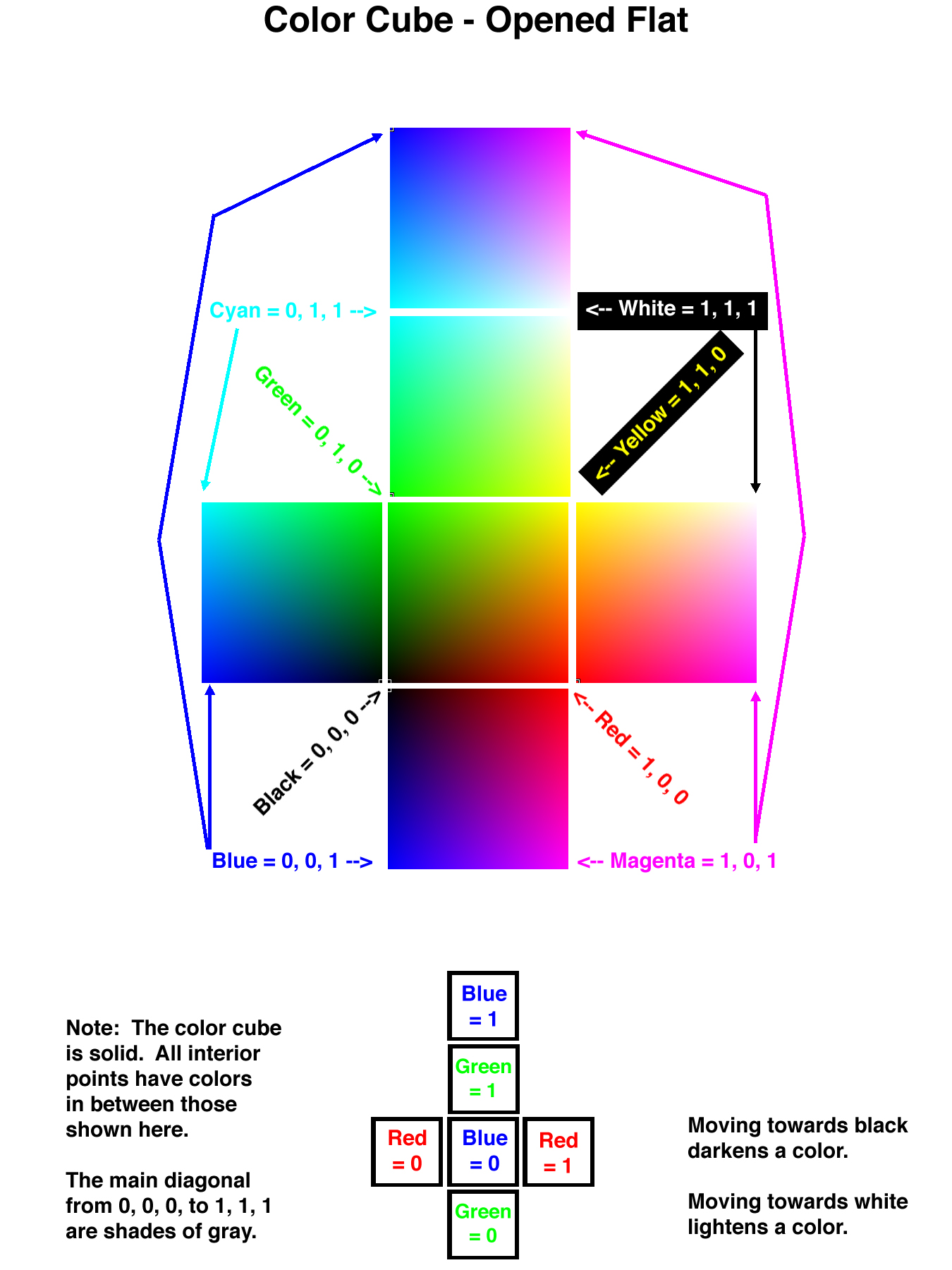
Each pixel of a simulation is rendered with a specific color and intensity, which are determined from a combination of the material of the object of which the pixel is a part, and the light shining on the pixel. The material properties describe how the object reflects different kinds of light, ( ambient, diffuse, or specular ), whether it emits light of its own, and what the transparency of the object is. These properties are combined with lighting information and rendering parameters to determine how to color each pixel, as shown on page 8-4 of the WorldToolKit manual. Let us examine each of these properties in turn:Ambient: The ambient color of an object indicates what color the object will appear under ambient white light.This can be considered to be the "base" color of the object.Ambient color is specified as three floating point values, from 0.0 to 1.0, representing the relative amount of red, green, and blue present respectively. ( A quick guide to color can be found on the linked illustration of the color cube. Further information will be provided in class. )
Diffuse: The diffuse color of an object indicates what color the object will appear under diffuse white light.The difference between ambient color and diffuse color is that the latter is affected by the angle at which the light strikes the object. ( Note that the angle of the viewer is not relevant for diffuse lighting, only the angle of the light itself. ) The diffuse color of an object is normally the same as its ambient color. Note also that ambient lighting is not sufficient for the diffuse property to be effective - Directed, point, or spot lighting are required.
( AmbientDiffuse may be specified to set both the ambient and diffuse properties to the same value. However, it is invalid to use the ambientdiffuse property and either the ambient or the diffuse property in the same material table. )
Specular: The specular color of an object indicates the color of specular highlights when a light is reflected off the object. Specular color is normally white ( 1.0 1.0 1.0 ), which means that the specular highlights are the same color as the light shining on the object ( which is also normally white. ) Specular contributions to a pixel's color are dependant upon both the angle at which light strikes the object and the angle at which it is viewed, as well as the object's shininess property ( see below ). Note also that either point or spot lighting are required for the specular property to have any effect.
Shininess: The shininess property of an object controls whether the specular highlights are tightly focused ( and sharply defined ), or whether they are more diffusely spread over a wider area. Shininess is implemented as an exponent in lighting calculations, and is specified as a floating point value from 0.0 to 128.0, with higher numbers indicating shinier objects.
Emissivity: The emissive property of an object determines how the object "glows" from within, in the absence of any external light source. Note that although emissive objects glow of their own accord, they do not illuminate other objects around them. The emmissive property is specified as a three-component color similar to ambient or diffuse.
Opacity: The opacity of an object indicates how much of the pixels behind the object show through to combine with the object's color information. Opacity is specified as a floating point value between 0.0 ( completely transparent ) to 1.0 ( completely opaque. )
Material Table File Format
An example material table file for the example given above might look like this:
mat
version 3.0
valid ambientdiffuse specular shininess opacitymatdef // id 0
ambientdiffuse 1.0 0.0 1.0 // Magenta
specular 1.0 1.0 1.0
shininess 100.0matdef // id 1
ambientdiffuse 0.0 0.0 0.0 // Black
specular 0.0 0.0 0.0
opacity 0.25Examples
Example files can be found under the recently modified cardemo directory.
Material Table Commands
There are many commands available in WTK for loading, manipulating, and/or saving material tables. Here are a few of the more useful ones:
Getting a Material Table
- WTmtable_new creates a new empty table, which can be subsequently filled with new entries.
- WTmtable_load loads a material table from a file.
- WTgeometry_getmtable gets the material table associated with a particular geometry.
- WTmtable_getbyname gets a material table based upon its name. The name is initially the name of the file a material table is loaded from, but this can also be changed later ( see below. )
Manipulating a Material Table
- WTmtable_getnumentries gets the number of materials in a material table.
- WTmtable_copyentry creates a new entry in a material table by copying an existing entry.
- WTmtable_newentry creates a new entry in a material table having all default values.
- WTmtable_merge merges two material tables into one.
- WTmtable_getproperties, WTmtable_setproperties determines which properties ( i.e. ambient, opacity ) are valid for a given material table.
- WTmtable_getvalue, WTmtable_setvalue are used to get and set specific values for specific properties for a specific entry of a material table.
- WTmtable_setname, WTmtable_getname are used to get and set the material table name. This is originally either NULL or the name of the file from which the material table was loaded.
- WTmtable_getentrybyname gets a material from a material table, based upon the name of the material.
- WTmtable_getentryname, WTmtable_setentryname are used to get and set the name of a particular material in a material table.
Using a Material Table to Modify Geometries / Polygons
- WTpoly_getmatid, WTpoly_setmatid are used to determine the material for a polygon
- WTgeometry_setmatid is used to set the material for a geometry.
- WTgeometry_getvertexmatid, WTgeometry_setvertexmatid are used to set the material for particular vertices of a geometry.
- WTgeometry_getmtable, WTgeometry_setmtable are used to determine the material table to be used for a geometry.
Saving ( or Discarding ) a Material Table
- WTmtable_setname is used to set the name of a material table, which is required before it can be saved. ( I.e. you cannot save a material table whose name is NULL. )
- WTmtable_save saves a material table to a file.
- WTmtable_delete deletes a material table from memory. ( It does not delete the file from the disk. )