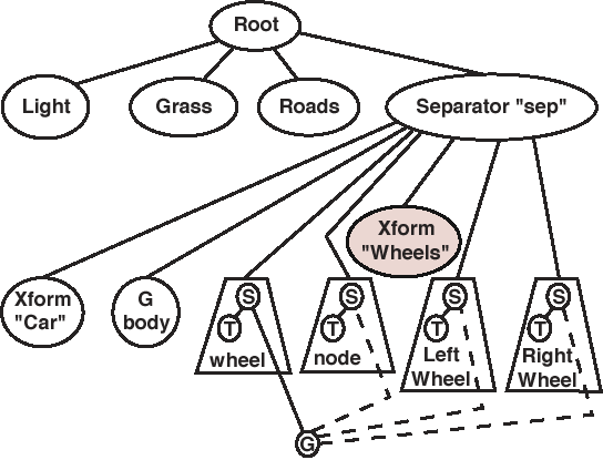
For this example it is desired to construct a simple car, consisting of a body and four identical wheels. The geometry of the body is defined centered about the X-Z origin, with the bottom of the car one unit above the Y origin, and with the car facing along the positive Z axis. The wheel geometry is defined with the center of the tire tread at the origin, aligned to roll along the Z axis, with a hubcap pointing along the X axis. The body has length 16, width 8, and height 5; The wheel has diameter 2 and thickness 1, plus an additional 1/2 for the hubcap.
The wheels will be instanced, and will have to be translated to the corners of the car (and up to ground level!) when they are loaded. Note that the wheels for the left side of the car also have to be rotated, so that the hubcap faces outward. In addition, the scene graph must be loaded so as to allow the car to be moved as a group, AND to allow the front two wheels to be turned from side to side ( as when the driver turns the steering wheel. ) After some trial and error, the following scene graph resulted:
The code to implement this example is in cardemo.c, and the supplemental files are in the cardemo directory.
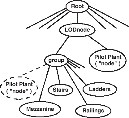
For this example a large chemical plant is modeled. The initial view is an aerial view, and there is one building that has a lot of detailed equipment inside. The detailed equipment is not visible from outside the building, but it still slows down the simulation when it is loaded into the scene graph. It is desired to use an LOD node, such that the details inside the building are only considered by the simulation when the user is sufficiently close to the building. The pertinent portion of the scene graph is as follows:
The code which generates this scene graph is shown below:
     /* The level-of-detail node has two children - One is just an empty pilot plant
	   building, and the other is a group node which encompasses the building and
	   all the contents.  The center and ranges are defined so that the building
	   contents only exist when the user is close to the building or inside */

	/* First set up the LOD node itself */

	LODnode = WTlodnode_new( root );
	WTlodnode_setrange( LODnode, LODranges, 2 );
	WTlodnode_setcenter( LODnode, center );

	/* Then the two children of the LOD node */

     /* This will be the highly detailed group */
	group = WTgroupnode_new( LODnode );

     /* The pilot plant building, stand alone low detail node */
	node = WTnode_load( LODnode, "PILOTPLT.NFF", 1.0 );

	/* Now start adding children to the group.
        Note: 1st child is pilot plant again */

     /* The pilot plant building, in the detailed group */
	WTnode_addchild( group, node );

	WTnode_load( group, "MEZZANIN.NFF", 1.0 );   /* Mezzanine */
	WTnode_load( group, "STAIRS.NFF", 1.0 );	/* Stairs & railings */
	WTnode_load( group, "RAILINGS.NFF", 1.0 );   /* Mezzanine railings */
	WTnode_load( group, "LADDER.NFF", 1.0 );	/* Mezzanine ladder */
For this example it is desired to set up a series of "question mark" icons for users to find and select. When a question has been selected, then three lights appear - red, yellow, and green in the standard "stop light" configuration. Users "answer" the question by selecting one of the lights. If their answer is correct, then the other two lights turn grey; If their answer is incorrect, then their selection turns grey, and they can choose again from the remaining two lights.
The scene graph is as follows:
The original code to generate this scene graph looked something like:
        /* Load up the questions */
        /* Eventually these will be read from a file */

        NQuestions = NQUESTIONS;        /* Integer */
        Questions = localQuestions;     /* Array of structures, with position, etc. */

        /* First load up the master copies.  Note that they are not
           connected to the scene graph. */

        QuestionMark = WTnode_load( NULL, "QUESTION.NFF", 1.0 );

        RedLight = WTnode_load( NULL, "RED.NFF", 1.0 );
        GreyRedLight = WTnode_load( NULL, "RED.NFF", 1.0 );
        WTgeometry_setrgb( WTnode_getgeometry( GreyRedLight ), 191, 127, 127 );

        YellowLight = WTnode_load( NULL, "YELLOW.NFF", 1.0 );
        GreyYellowLight = WTnode_load( NULL, "YELLOW.NFF", 1.0 );
        WTgeometry_setrgb( WTnode_getgeometry( GreyYellowLight ), 191, 191,127 );

        GreenLight = WTnode_load( NULL, "GREEN.NFF", 1.0 );
        GreyGreenLight = WTnode_load( NULL, "GREEN.NFF", 1.0 );
        WTgeometry_setrgb( WTnode_getgeometry( GreyGreenLight ), 127, 191, 127 );

        /* Now to build the scene graph. */

        QuestionsNode = WTgroupnode_new( root ); /* Global pointer to group node */

        for( i = 0; i < NQuestions; i++ ) {    /* Loop through array of Questions */

                /* First the separator and transform nodes */

                sep = WTsepnode_new( QuestionsNode );
                node = WTxformnode_new( sep );
                WTnode_settranslation( node, Questions[ i ].translation );
                WTnode_setorientation( node, Questions[ i ].orientation );

                /* Then the question mark geometry */

                WTnode_addchild( sep, QuestionMark );

                /* And then the red, yellow, and green lights */

                node = WTswitchnode_new( sep );

                WTnode_addchild( node, RedLight );
                WTnode_addchild( node, GreyRedLight );
                /* WTswitchnode_setwhichchild( node, GREY ); */
                /* Default switch when switchnode created is NONE */
                /* GREY is #defined as 1, BRIGHT as 0 */

                node = WTswitchnode_new( sep );
                WTnode_addchild( node, YellowLight );
                WTnode_addchild( node, GreyYellowLight );
                /* WTswitchnode_setwhichchild( node, GREY ); */

                node = WTswitchnode_new( sep );
                WTnode_addchild( node, GreenLight );
                WTnode_addchild( node, GreyGreenLight );
                /* WTswitchnode_setwhichchild( node, GREY ); */

        }
Notes: